


The 555 Astable generates a clock for this circuit, an oscillator giving a square wave output at pin 3 which is counted by 4017 to give a running lights effect.
The decade counter-divider CD4017 has 10 outputs, for every low to high transition at the clock input, rising edge, the counter advances one LED. After going one full circle the the first LED lights again and it goes on. You can vary the value of R2 100K Linear potentiometer to make LEDs run fast or slow. The frequency of oscillation of astable 555 is given as f = 1.44 / ((R4 + 2 * (R2 + R3)) * C3)
The 10 outputs have 10 green LEDs. The current thru the LED is limited by R1, the current can be calculated like this (9V - 1.6V) / 1K = 7.4mA this is within 20mA which is the danger limit of the CMOS output. You want it to be bright use transistors for every output.
The cap C1 is a filter and C2 is to prevent noise at pin 5 influencing the output as it is a control voltage point.
You can cascade or chain many more counters with the CO or carry out pin 12 of 4017. The pin 15 reset is kept at low for counting, on high it will reset the counter but is not used in this circuit.
more...

berikut ini adalah rangkaian inverter 12V to 220V 100W dengan menggunakan Transistor. Rangkaian ini memang cukup membingungkan tetapi bila anda mau mencoba pasti besar manfaatnya bila di aplikasikan.trafo yang digunakan adalah trafo CT.selamat mencoba....
berikut ini adalah rangkaian inverter 12V to 220V 100W dengan more...

The speed of an automobile can be indicated by detecting the pulses generated by the ignition system and causing an LED to light. The circuit utilizes a quad NOR gate IC chip. Two of the gates are configured as a one shot multivibrator which produces a fixed duration pulse each time the primary circuit of the automobile ignition system opens the circuit to the ignition coil. The other 2 gates are used as buffers which provide an accurate rectangle pulse. As the number of pulses per second increases, the voltage fed to the base of of the NPN transistor becomes high enough to cause it to conduct and turn on the LED. The speed at which the LED lights is set by R4. The input of the circuit is connected to the distributor side of the ignition coil or to the tachometer connection on those cars that are equipped with electronic ignition.
more...

Wireless portable unit
Adaptable with most internal combustion engine vehicles
Parts:
R1,R2,R19_______1K 1/4W Resistors
R3-R6,R13,R17_100K 1/4W Resistors
R7,R15__________1M 1/4W Resistors
R8_____________50K 1/2W Trimmer Cermet
R9____________470R 1/4W Resistor
R10___________470K 1/4W Resistor
R11___________100K 1/2W Trimmer Cermet (see notes)
R12___________220K 1/4W Resistor (see notes)
R14,R16________68K 1/4W Resistors
R18____________22K 1/4W Resistor
R20___________150R 1/4W Resistor (see notes)
C1,C7_________100µF 25V Electrolytic Capacitors
C2,C3_________330nF 63V Polyester Capacitors
C4-C6___________4µ7 25V Electrolytic Capacitors
D1,D5______Red LEDs 3 or 5mm.
D2,D3________1N4148 75V 150mA Diodes
D4________BZX79C7V5 7.5V 500mW Zener Diode
IC1__________CA3140 or TL061 Op-amp IC
IC2____________4069 Hex Inverter IC
IC3____________4098 or 4528 Dual Monostable Multivibrator IC
Q1,Q2_________BC238 25V 100mA NPN Transistors
L1_____________10mH miniature Inductor (see notes)
BZ1___________Piezo sounder (incorporating 3KHz oscillator)
SW1____________SPST Slider Switch
B1_______________9V PP3 Battery (see notes)
more...

Driving the highway with your high-beam headlights can really increase your visibility, but can he a blinding hazard for other drivers. This simple circuit can be wired into your headlight switch to provide automatic switching between high and low beam headlights when there is oncoming traffic. It does this by sensing the lights of that traffic. In this way, you can drive safely with your high-beams on without blinding other drivers.
Parts:
R1 5K 1/4W Resistor
R2, R3, R4 5K Pot
Q1 NPN Phototransistor
Q2 2N3906 PNP Transistor
K1 Low Current 12V SPST Relay
K2 High Current 12V SPDT Relay
S1 SPST Switch
B1 Car Battery
MISC Case, wire, board, knobs for pots
more...

he circuit above is an automatic switch which functions in absence of light. The IC 4060 works as an oscillator and the generated signal is applied to the base of T4 transistor. Phototransistor T3 is in conduction by existance of light and it keeps the T5 transistor’s base at ground potential.
When no light reachs the phototransistor, it gets in insulation. T3 reachs positive potential through 22kohm. T4 and T5 both gets in conductance. The oscillator signal reachs the optic coupler and lamp(s) shines.
more...
.jpg)
Contain divide this friends many you may face a problem economical. A steal the very. Today I then beg for to advise the circuit protects steal again model that interesting. It is model to touch , the system will work when , steal touch at the metal detects. When you see the circuit may like ,because use the equipment that seek easy be IC 741 very the circuit has tall many rapidity. When human body which there is electronic signal flows through all the time , make that signal changes to come to at input change R4 to pin 3 of IC LM741 make it works cause Q1 and oval RY1 work with. The lead goes to are usable , friends fine VR1 for fix the rapidity has of the circuit. The detail is other see in the circuit has please yes.
more...

The second circuit simulates the siren of an American police car. It uses two 555 timers in the circuit. The 555 on the right is wired as an alarm tone generator and the second 555 timer on the left is wired as a low frequency astable timer which generates a ramp waveform of about 6 seconds that is buffered by the transistor and again used to frequency modulate the tone generator. The transistor is used to help strengthen the signal to the speaker
more...

Double-tone Police sound
Single-tone old ambulance sound
This circuit is intended for children fun, and can be installed on bicycles, battery powered cars and motorcycles, but also on models and various games and toys. With SW1 positioned as shown in the circuit diagram, the typical dual-tone sound of Police or Fire-brigade cars is generated, by the oscillation of IC1A and IC1B gates. With SW1 set to the other position, the old siren sound increasing in frequency and then slowly decreasing is reproduced, by pushing on P1 that starts oscillation in IC1C and IC1D.
The loudspeaker, driven by Q1, should be of reasonable dimensions and well encased, in order to obtain a more realistic and louder output. Tone and period of the sound oscillations can be varied by changing the values of C1, C2, C5, C6 and/or associated resistors. No power switch is required: leave SW1 in the low position (old-type siren) and the circuit consumption will be negligible.
Parts:
R1,R3___470K 1/4W Resistors
R2______680K 1/4W Resistor
R4_______82K 1/4W Resistor
R5______330K 1/4W Resistor
R6_______10K 1/4W Resistor
R7_______33K 1/4W Resistor
R8________3M3 1/4W Resistor
C1,C5_____10µF 25V Electrolytic Capacitors
C2,C6_____10nF 63V Polyester Capacitors
C3_______100nF 63V Polyester Capacitor
C4_______100µF 25V Electrolytic Capacitor
D1-D3___1N4148 75V 150mA Diodes
IC1_____4093 Quad 2 input Schmitt NAND Gate IC
Q1______BC337 45V 800mA NPN Transistor
P1______SPST Pushbutton
SW1_____DPDT Switch
SPKR____8 Ohm Loudspeaker
B1______6V Battery (4 AA 1.5V Cells in series)
more...
![]()
When you are born electricity problem switches off, should seek the system Emergency give the light. I begs for to advise Mini Emergency Light. By use electronics part, general seek easy and have no transformer. Then make this circuit has small-sized and economize very. From this circuit use power supply 3V then apply to lamp 2.4V 5W only. And friends can use Nicad Battery or , NiMH battery the size is 1.2V x 2 give the light has just enough. When the electricity switches off the system command give lamp stick bright get. The SW1 use for turn on or turn off this circuit. A friend may use this circuit help offer the convenience your please sir.
more...

Parts:
R1,R3____________1K 1/4W Resistors
R2,R5___________10K 1/4W Resistors
R4_____________220R 1/4W Resistor
R6_____________220K 1/4W Resistor
R7______________22K 1/4W Resistor
R8_____________100K 1/4W Resistor
C1,C2___________22µF 25V Electrolytic Capacitors
C3______________10nF 63V Polyester or Ceramic Capacitor
C4______________47µF 25V Electrolytic Capacitor
Q1,Q2_________BC557 45V 100mA PNP Transistors
Q3____________BC337 45V 800mA NPN Transistor
SW1___________SPST Toggle or Slide Main Switch (See Notes)
P1____________SPST Pushbutton Operating Switch
SPKR__________8 Ohm Loudspeaker
B1____________12V Battery
more...


Car Burglar Alarm timer alarm system circuit , model to economize. This circuit convenients for to set up in an automobile. usually switch at set up keep with automobile door will the circuit closes. But in case of car owner opens in and out while note as a result have no result anything , because of the transistor model PNP to still don’t work. Because of 9 pin have high voltage. But when switch the door any one open the circuit exceed time delay keep 5 pin of IC NE556 have low voltage to fully drive transistor circuit give relay work. The system will order to give the horn a car talks at one time to come to immediately. But if we shut the door a car or close S1 system stop work again.
more...
.jpg)
This be Random Number Generator Circuit there is the character is 10 LED Flasher by use IC 4017 and IC 4011. For the 4017 IC is a 16-pin CMOS decade counter. It takes clock pulses from the clock input, and makes one of the ten outputs come on in sequence each time a clock pulse arrives. Usability press S1 for LED Flasher respectively. By pressure (Close) S1 make LED all stick dim (Dimly). When liberate (open) S1 make LED stick bright at LED any one to one’s fate. Besides value expansion C1 be 4.7uF make LED flasher slow down. The detail is other invite friends see in the circuit leisurely.
more...

This is lamp flasher circuit. It is use transistor 2 pcs. For the system shows matters for objection which rub encourage give work by the alarm. An officer will take the alarm by pressure the Secretariat of the switch Sa. Which will change a light bulb from the winking to sticking bright is unfinished. a tube is model 6V size entrailses will pull the trend s about 0.3A change transistor Q2. But a resister that is load of transistor Q1 that will limit the trend that change the transistor 6mA very thus. Then transistor that have small-sized can get down.
more...

This the circuit light led flashing ,with show of 10 LED. By use integrated number circuit CD4017 perform be Decade Counter/Divider with 10 Decoded Outputs. Which it is integrated digital circuit CMOS then use the power supply about 9VDC. For a signal input continue the circuit can produce general frequency may use IC NE555 all right.
more...

The circuit uses a 555 timer oscillator to supply clock pulses of a variable frequency to the 4017 decade counter. The decade counter only needs to have three outputs so the fourth output goes into the reset pin to start the cycle all over again. The central red led is always on. Each row of four leds flash in sequence giving the impression that the light is rotating. It is an idea that works very well giving an eye-catching display. It will run continuously for three hours with a standard pp3 battery.
more...
Today I begs for to advise 6 Light Running Circuit. It suits the festival for the beauty and good strange-looking. It use IC 4017, IC 555 for Pulse Generator give with IC 4017 Display Lamp with SCR Circuit. FOR Drive Lamp 220V 650Watt per Lamp channels. For VR1- 100K perform fine decorate the speed of Lamp 220V follow want. This circuit is model to simple, but must be careful relate home Lamp.
more...
Use a electronics part ,easy to find and low cost.
To See Circuit, have IC 555, 4017, 4011 and BC337,BC327.
Output Piezo Speaker.
Volt suppy +12V.
This is Circuit MOSQUITO REPELLANT.
By High Frequency Sound.
PCBnya :
 more...
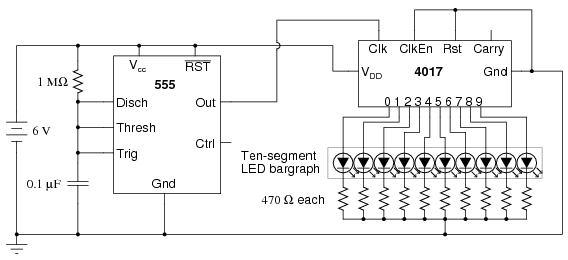
PARTS AND MATERIALS :
- 4017 decade counter/divider (Radio Shack catalog # 276-2417)
- 555 timer IC (Radio Shack catalog # 276-1723)
- Ten-segment bargraph LED (Radio Shack catalog # 276-081)
- One SPST switch
- One 6 volt battery
- 10 kΩ resistor
- 1 MΩ resistor
- 0.1 µF capacitor (Radio Shack catalog # 272-135 or equivalent)
- Coupling capacitor, 0.047 to 0.001 µF
- Ten 470 Ω resistors
SCHEMATIC DIAGRAM
selamat mencoba
http://www.finalsense.com/services/blog_templates more...
Saya tidak tahu mengapa, tetapi orang-orang seperti lampu berkedip. LED chasers anda lihat di mana-mana, di TV menunjukkan (Knight Rider), film, dan jendela toko. Skematis ini adalah versi sederhana 10 LED chaser. Tidak ada 555 karena waktu yang digunakan di toko elektronik lokal mereka lebih dari $ 4 CDN. Sebaliknya, sebuah osilator terdiri atas dua bagian dari 4011 gerbang NAND adalah bekerja. Chip ini sangat murah dan sangat umum.
Bagian :
Bagian Total Qty. Keterangan Substitutions
R1 1 1 Meg resistor 1/4W
R2 1 100K Pot
R3 1 Resistor 1K 1/4W 220Ohm jika menggunakan blue LEDs
C1 1 0.1uF 16V Ceramic Disk kapasitor
U1 1 4011 CMOS NAND Gate
U2 1 4017 CMOS Counter
LED1-10 10 LEDs Of Any Colour
MISC 1 Board, Socket Untuk ICS, Knob Untuk R2
Catatan :
Gunakan R2 untuk menyesuaikan "chase menilai".
Anda mungkin perlu menggunakan nilai resistor yang lebih rendah jika Anda ingin menggunakan LEDs biru. Coba 220 Ohm.
Anda juga dapat menggunakan lampu pijar daripada LEDs. Transistor gunakan untuk mengarahkan mereka dengan menghubungkan dasar Transistor ke masing-masing output dari 4017 melalui 1K resistor. Hubungkan satu ujung lampu ke pasokan positif. Kemudian hubungkan ujung yang lain ke kolektor dari transistor. Emitter yang kemudian pergi ke tanah. Tergantung pada lampu, Anda mungkin perlu daya Transistor yang panas sinked.
C1 dapat diganti dengan nilai yang lebih besar untuk lambat "chase menilai".
Jika Anda memiliki masalah dengan sirkuit perilaku aneh, coba ganti R1 dengan resistor 33k, dan meningkatkan C1 ke 1uF.
Jika Anda berencana untuk menggunakan sirkuit ini di mobil Anda, akan memberikan peringatan bahwa di beberapa daerah itu adalah ilegal untuk memiliki warna merah, biru, kuning atau lampu kilat, kecuali jika Anda adalah sebuah kendaraan darurat.

Di sirkuit yang di bawah cahaya lampu 20 watt bila kontak dan menyentuh kulit perlawanan adalah sekitar 2 Megs atau kurang. Sirkuit yang di sebelah kiri menggunakan MOSFET daya yang berubah pada saat tegangan antara sumber dan gerbang sekitar 6 volts. Pintu gerbang yang mengacu MOSFET tidak ada saat ini sehingga tegangan pada gerbang akan setengah pasokan tegangan atau 6 volts ketika perlawanan di seluruh kontak sentuh adalah tetap sama dengan perlawanan (2 Megs) antara sumber dan gerbang.
Sirkuit yang di sebelah kanan menggunakan tiga Transistor bipolar untuk mencapai hasil yang sama dengan sentuhan kontak dirujuk ke negatif atau tanah akhir pasokan. Karena dasar dari transistor bipolar mengacu pada saat ini saat ini dan biasanya memperoleh kurang dari 200, tiga Transistor dibutuhkan untuk meningkatkan tingkat microamp melalui sentuhan kontak ke beberapa amps diperlukan oleh terang. Tambahan untuk saat ini, lampu bisa diganti dengan 12 volt relay dan diode di seluruh gulungan.

berikut ini adalah membuat timer menggunakan 555.Ketika pin 2 disulut membuat pin 3 tinggi.
Rumus: 1,1 x R1 x C1(Farad) = waktu dalam detik.
IC 555 dapat mengeluarkan arus sebesar 200ma.
thx...
vivitors map

count down !
Make your own Countdown Clocks

